|
|
|
Instrument Description
|
|
 Principle of Operation Principle of Operation
Instrument Overview
Gun Detector Units
Electron Guns
Electron Detectors
Controller
Correlators
Tracking Operation
Ambient Particle Measurements
|
|
|
|
|
|
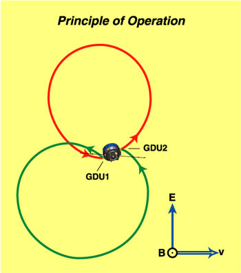
Figure 1

|
|
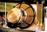
Principle of Operation
The electron drift instrument measures the displacement of a weak (< 1 µA) beam of test electrons, after one gyration in the ambient magnetic field that is induced by electric fields or magnetic gradients. This displacement (the drift step) causes the beam to return to a detector on the spacecraft only when emitted in one of two precisely determined directions. By employing two beams and two detectors, these directions can be monitored continuously and the displacement obtained by triangulation. Figure 1 illustrates the situation.
For small magnetic fields the triangulation degenerates and the displacement is obtained instead from the difference in the travel times of the electrons in the two beams. As a by-product, the measured times-of-flight provide a precise measurement of the magnetic field magnitude.
The electron energy is switched between 1.0 and 0.5 keV. As the electric field drift does not depend on electron energy, while the gradient drift does, this scheme allows to separately determining the electric fields and the magnetic field gradients.
The diagram in Figure 2 shows characteristic relations between the magnitude of the ambient electric and magnetic fields and the drift step.
|
|
Figure 2
|
|
|
 |
|
|
 |
|
|
Instrument Overview
MPE's contributions are the electron guns; the HV-supplies for the guns and detector optics; the correlators; instrument integration and testing; the tracking simulator; overall responsibility and management. UCSD had responsibility for design, fabrication and calibration of the detector optics. Lockheed designed the sensor system. For Cluster-II, UNH took over responsibility for sensor fabrication and testing. UNH designed and built the Controller and the spacecraft simulator, and had prime responsibility for the on-board software,
|
|
|
|
|
|
|
|
|
|

Figure 3

|
|
Gun Detector Units
The essential elements of the instrument are two electron guns, two detectors with their associated analogy electronics, high-voltage supplies, digital controls, and correlators, and a controller unit that includes the interfaces with the spacecraft and with other instruments.
Guns and detectors are combined in pairs into a single unit, referred to as the gun/detector unit (GDU). The two GDUs are mounted on opposite sides of the spacecraft.
Figure 3 shows a cross-sectional view of a gun/detector unit (GDU). The cylindrical section at the top is the electron gun, with its filament and control electrodes at the bottom of a long drift tube from where the electrons enter the octopole deflector before they are slowed down and further deflected by the curved retarding grid. A collar that bridges the detector aperture supports the gun. Independently selectable voltages on 9 electrodes determine the optical properties of the detector: the polar angle of its look direction, the sensitive area for parallel beams, and the energy-geometric factor for ambient particles. An annular MCP followed by a ring of 128 discrete anodes detects the electrons at their azimuth angle of arrival.
Figure 4 shows two Gun-Detector Units, together with the Controller, before environmental testing in MPE's thermal-vacuum chamber.
|
|
Figure 4
|
|
|
|
|
|
|
|
|
Electron Guns
In order to be able to aim the beam at the target for arbitrary magnetic and electric field directions, the electron guns must be capable of providing a beam that can be steered rapidly into any direction within more than a hemisphere.
A design meeting these requirements is illustrated at the top of Figure 3. To our knowledge this is the first electron gun capable of providing narrow beams in any direction within more than a hemisphere. A conventional electron source, consisting of a tungsten cathode and several electrodes (Wehnelt, Focus, and Anode) is used to produce a narrow beam at 2.7 times the required energy. The electron energy is set by the cathode potential and can be varied between 0.5 and 1.0 keV. The beam current is controlled via the current applied to the tungsten filament and can be varied between 0.1 and 1000 nA. The beam is intensity-modulated by superposing the code-signal from the correlator onto the static Wehnelt voltage via a fiber-optic cable.
After exiting from the anode, the beam is deflected into the desired azimuth direction by an octopole arrangement of electrostatic deflectors. The electrons then approach a high-transmission grid at ground potential. This retarding potential decelerates the electrons to their final energy. Since it is mainly the energy along the symmetry axis that is removed when the electrons approach the grid, the deflection angle is amplified.
The deflection grid is made of fine copper-beryllium wires woven into a mesh that is then formed into a basket shape, welded to a steel flange, and finally gold-plated. The gun voltages are generated by individual high-voltage amplifiers that use the light from LEDs to control the leakage current of two high-voltage (HV) diodes connected in a push-pull configuration between the plus- and minus-sides of a HV stack.
|
|
|
|
|
|
|
|
|
|
Electron Detectors
The detector must be able to look in any direction within a region greater than a 2pi steradian hemisphere and change their look directions in less than a millisecond. To compensate for the low returning beam fluxes, the detectors must have a large effective area, as much as two or three square centimeters.
The detector system that we designed to meet these requirements is illustrated in Figure 3. It consists of an optics section, a programmable sensor, associated electronics, and voltage generators. Adjustment of the look direction is achieved in elevation by deflecting the incoming beam, and in azimuth by selecting a contiguous set of sectors of the annular image-region on the sensor micro-channel plate (MCP). The incoming beam of electrons is monoenergetic and monodirectional, and illuminates the entire detector.
Nine independently programmable high-voltage supplies are needed to operate the optics subsystem. A tenth programmable supply sets the sensor-reference voltage. For electron drift measurements, all voltage except the sensor reference are scaled with energy; the voltage on the latter is kept fixed because its capacitative time constant does not permit rapid changes. Although all ten electrode voltages can depend on polar angle, in order to conserve controller resources we vary only the five that depend most strongly on polar angle (deflectors, injectors and retainer cone). All voltages are generated by the same type of HV supplies already referred to in the Gun section.
For a given beam energy and polar angle, different combinations of these voltages can be chosen to obtain different collection areas for the beam and different geometrical factors for the ambient (`background') electrons. Therefore, with appropriate combinations of voltages we can optimize beam-signal levels or signal-to-noise (SNR) levels, depending on the circumstances. We use a finite number of such voltage combinations, called optics `states'.
Electrons are imaged by the detector optics onto an annular microchannel plate (MCP). Under command of the controller, the sensor responds only to events within a selected azimuthally range, thus complementing the polar angle selection that is performed by the optics. The sensor collects the amplified electron events, which are produced by the MCP stack operated in the pulse-counting mode, on an annular array of 128 discrete anodes.
|
|
|
|
|
|
|
|
|
|
Controller
Based upon information from the detectors and the on-board magnetometers, the controller programs the guns and detectors. It establishes beam coding and tracking patterns and handles all interfaces with the spacecraft and with other instruments. We use a Sandia 3300, a radiation-hardened version of the NSC 32C016, as our central processor. The associated memory has 8 kB of fuse-linked PROM, 160 kB of EEPROM, and 32 kB of static RAM. The fuse-linked PROM contains the software for system initialization, housekeeping, and basic telemetry routines. The EEPROM, which is reprogrammable via spacecraft commands, contains three types of information. The controller includes 1 MB of non-hardened memory for storage of burst mode or diagnostic data.
The controller communicates with the spacecraft, with other instruments, and with the gun/detector electronics. The spacecraft interface handles all science and housekeeping telemetry as well as inputs such as time tagging and commanding. Inter-experiment links include magnetic field information from FGM and STAFF, a blanking pulse from WHISPER to warn of possible interference from that active experiment, and a blanking pulse sent from EDI to PEACE when the EDI electron beam could interfere with the PEACE electron measurement. The interface with the GDUs consists of three optical-fiber cables for each GDU, carrying serial information.
The fundamental functional time step of the EDI instrument is the controller's basis cycle interrupt (BCI), which is nominally 2 or 4 ms. Every BCI, the controller will use the information it receives from the various interfaces to calculate new parameters for directing the beams and the detectors. Tracking tasks operate on longer time scales, such as slowly changing the beam current or modifying the detector's basic optics state.
|
|
|
|
|
|
|
|
|
|
Correlators
To detect the beam electrons in the presence of background counts from ambient electrons and to measure their flight time, the electron beam is intensity-modulated with a pseudo-noise code (PNC). The modulation is achieved by changing the Wehnelt control voltage such that the beam is successively turned on and off. In order to reject detector signals from the gun in the same unit, the codes for the two gun-detector pairs are inverted relative to each other. The modulation frequency can be chosen between 8 kHz and 4 MHz in order to cover the range of expected time delays and to obtain adequate delay-time accuracy.
The stream of electron event pulses received by the detectors are fed in parallel into an array of counters, each one gated with its individual copy of the PNC, shifted by one chip from counter to counter, and delayed as a whole (by a variable amount) against the PNC used to modulate the outgoing beam. The counter that is gated with a PNC matching the flight time will receive all the beam event (`signal') plus half the background events, while all others receive only half the signal plus half the background. A drift and tracking control loop (`auto-track') varies the delay of the correlator codes relative to the gun code such that the signal is kept in one dedicated counter while the flight time changes as a result of changing magnetic and electric fields.
|
|
|
|
|
|
|
|
|
|
|
Figure 5
|
Tracking Operation
Figure 5 illustrates of the Windshield-Wiper mode of operation. The electron beam from GDU1, characterized by its current, speed, direction, width , modulation frequency and code-type, is swept in the plane perpendicular to the magnetic field, as determined from the FGM and STAFF magnetometers. Signals recorded by the detector in GDU2 are analyzed to determine when the beam is on target. A similar link (not shown) exists between the gun in GDU2 and the detector in GDU1. The detector count rate consists of the background signal from the flux of ambient plasma electrons and the beam signnal from the incident flux of beam electrons if the beam is on target.
Correlators are used to distinguish beam and background electrons, as well as to measure the time-of-flight of the beam electrons. Once beam passage has occurred, the sweep direction of the beam is reversed and the process repeated, as indicated in the box at the top of the figure. For small E/B, the return beam is directed parallel to the emitted beam, but for large E/B there is a significant offset. Every 4 ms the controller exercises a software loop that directs beams and detectors, and sets the correlator parameters. A navigation task running every 250 ms selects beam currents, optics states, etc.
To recognize that the beam is returning to the detector, the controller constantly (once every 2 ms) computes the signal-to-noise ratio from the maximum and minimum counts in the set of correlator channels. If that ratio exceeds some (selectable) limit, it is assumed that the beam is striking the detector.
The `windshield-wiper' software, which keeps the target direction tracked in angle space, is interwoven intricately with the time-tracking software, which keeps the time-of-flight information available. As noted earlier, the beams are modulated with a coded waveform. Correlating the received signal, after a delay corresponding to the time of flight, with the original coded signal, has two important functions. First, correlating the return signal with the fired signal allows a significant increase in signal-to-noise ratio. Second, the delay that results in the largest correlated signal corresponds to the time of flight of the electron beam. In the WW-mode, telemetered data consist of the firing angles when the two beams were on target, and the two associated electron times-of-flight, plus timing, countrate and quality information.
With the allocated telemetry rate it is possible to transmit this set of measurements every 64 ms in nominal-mode (NM) telemetry and every 16 ms in burst-mode (BM1) telemetry. From the telemetered data one can then derive the drift velocities and the magnetic field strength, in BM1 telemetry and under ideal tracking conditions as often as every 16 ms.
|
|
|
|
|
|
|
|
|
|
Ambient Particle Measurements
The EDI detectors are capable of measuring both electron and ion particle distributions. Each of the two detectors can be commanded to look in any direction over greater than a 2 pi steradian hemisphere, and since the two detectors are mounted on opposite sides of the spacecraft with their symmetry axes pointing in opposite directions, full-sky surveys can be achieved without relying on spacecraft spin to complete the coverage of phase space. In addition, since the magnetic field is known to the EDI controller via the on-board magnetometer data, specialized surveys can be performed in coordinates fixed with the magnetic field, and they can be performed continuously.
|