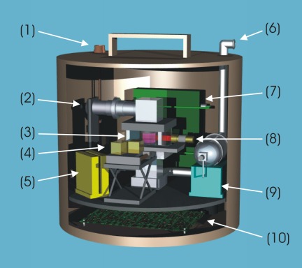
Schematic view into the PKE-Nefedov Experimental Block |
|
|
Fig.1: The PKE-Nefedov hardware onboard the ISS consists of
two components: the Experimental Block and the so-called Telescience
Module. The Experimental Block is shown in the figure. It can be divided
into three different parts: Part I: Experimental setup. Includes the rf plasma chamber (3, see also Fig.2), a symmetrical parallel plate reactor filled with argon with assembled microparticle dispensers (2 = dispenser drive), rf-generator (7), pressure control system (9), cameras (4), and lasers (8) mounted on a translation stage. The rf generator is a special development for lowest rf power values, which are required for stable and large complex plasma systems and for plasma crystal formation. Two CCD-cameras provide two different magnifications of the complex plasmas. The overview camera shows about a quarter of the field between the electrodes, 28.16 x 21.45 mm2, while the high resolution camera is used for detailed views inside the overview field covering 8.53 x 6.50 mm2. On top of the Experimental Block a vacuum connection (6) is used to pump the experimental setup. This vacuum port is contacted to outer space. Part II: Electronics (5, 10) for part I and the system electronics (PC, video and main power control). Part III: Experiment computer. Allows real time control of the plasma. Electrical signals produced by the experiment computer and the two video signals are contacted out of the container (1) and are controlled by the Telescience Module (see Fig.4). The computer visualizes the experimental data and can be used to control the experiment manually. Time codes (VITC signals) are inserted into the video frames and stored on two High-8 video recorders. The original video tapes are transferred to ground by the cosmonauts. The Telescience Module has the capability to transfer experimental data and video to ground and receive commands from ground, allowing full telescience control of the experiment by the scientists. |
Monodisperse particles of different sizes – 3.4 µm and 6.8
µm in diameter, as well as a mixture of both sizes – can be
injected into the plasma chamber, between the two electrodes.
The microparticles are illuminated by a thin (~150 µm) sheet of laser
light perpendicular to the electrode system (produced by a laser diode
and cylindrical optics). For each particle size one laser is installed,
which is adjusted in power and optics to achieve best results. The
reflected light from the microparticles is observed with two
monochromatic video CCD-cameras (768 x 576 pixels, 25 Hz, 8-Bit) with
different resolution. The microparticles can be identified in a single
video frame and are then followed in time to investigate their dynamical
behaviour. The frame rate is 25 Hz, which is faster than the complex
plasma frequency of ~10 Hz. Slow speed scanning of the laser and optics
into the depth of the plasma chamber is used to measure the 3D
positions of the microparticles.
|
Scheme of the PKE-Nefedov Plasma Chamber |
|
|
Fig.2: Cross section through the heart of the PKE-Nefedov
experiment: the plasma chamber ((3) in Fig.1). This is a square
vacuum chamber with a size of 10 x 10 cm2
made of glass. The rf electrodes are flat circular plates, made
from stainless steel, with a diameter of 4.2 cm, where a dust
dispenser is integrated in the center of each side.
The microparticles are injected into the discharge region between
the electrodes by an oscillating up and down motion of the dispensers.
The particles are accelerated inside the reservoir and released
through a sieve with a meshsize slightly larger than the particle
diameter. The electrode distance is 3 cm. The
excentric field of view of the CCD cameras is shown here in green. |
 |
The Actual Experiment Hardware |
|
|
Fig.3: Here we see the PKE-Nefedov experiment hardware before
integration into its sealed cylindrical containment. On the left side
there is the CCD camera electronics connected to both CCD cameras
that are looking into the plasma chamber (center). On the right side
there is the gas supply system (with the argon gas bottle) that is
connected on the ground to a vacuum pump. On the
ISS the experiment is connected directly to open space. (Unfortunaletly,
the vacuum port onboard the ISS is a rather narrow line which made it
necessary to upgrade PKE-Nefedov with a turbo-molecular pump at the
vacuum port. This pump was installed in Sept. 2001.) The hardware was built by MPE and |

|
PKE-Nefedov and the Telescience Unit |
|
|
Fig.4: PKE-Nefedov and its control and data acquisition system,
the Telescience Unit. The naming is due to the fact that the experiment
can totally be run from this unit which can be at any remote place. The
original plan was to operate PKE-Nefedov in orbit from the Telescience
Unit on the ground via a satellite link, but unfortunately the satellite
failed so that only a telemetry mode could by established.
The Telescience Unit was also carried into orbit and the data tapes
were then taken to earth by the returning ISS crew. |
 |
|
|
|
")